Case Description
Technical Case Study: T56 Reduction Gear Assembly Hydraulic Pump1. Component Location
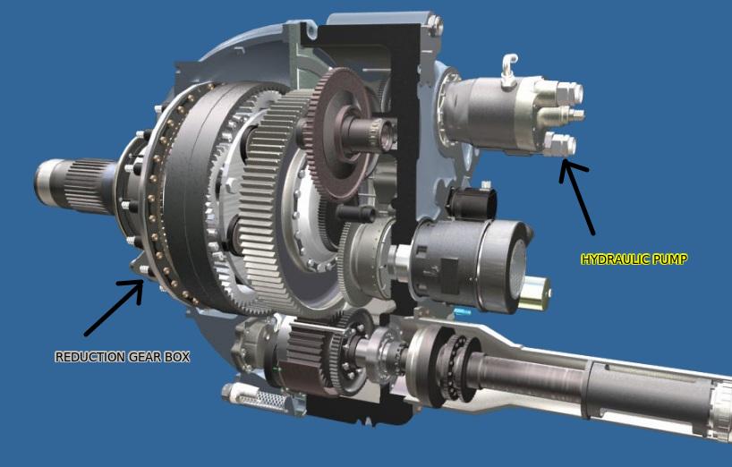
Each T56 engine is equipped with one hydraulic pump mounted on a dedicated accessory pad located on the rear case of the Reduction Gear Assembly (RGA)
. Based on the RGA's rear face layout, the mounting pad for the hydraulic pump is positioned at the top of the assembly
. The remote location of the RGA—connected to the power section by the torquemeter assembly—provides the additional space required to mount these accessories without increasing the engine's frontal area or affecting air inlet efficiency
.
2. Primary Functions
The primary function of the engine-driven hydraulic pump is to supply the normal operating pressure for the aircraft's hydraulic systems during all phases of flight
. These pumps convert the mechanical rotation of the engine into hydraulic power, which is essential for the operation of critical aircraft components such as landing gear, flaps, and flight control surfaces [142, Conversation History].
3. System Assignments (Utility vs. Booster)
The hydraulic pumps are integrated into the C-130's hydraulic architecture according to the engine number on which they are installed. This distribution ensures that hydraulic pressure is maintained even if one or more engines are shut down:
Utility System: The hydraulic pumps located on Engines No. 1 and No. 2 are responsible for supplying pressure to the aircraft's Utility Hydraulic System
.
Booster System: The hydraulic pumps located on Engines No. 3 and No. 4 are responsible for supplying pressure to the aircraft's Booster Hydraulic System
.
4. Operational Drive Mechanism
The hydraulic pump is driven by the pinion gear input shaft through a specialized gear train located within the RGA
. Specifically, rotational energy is transmitted from the pinion shaft to a hydraulic idler gear, which then meshes with the hydraulic pump drive gear
.
The operational speed of the pump is determined by the specific tooth count of these gears, ensuring that the pump rotates at its optimal RPM whenever the engine is operating at its 100% rated speed (13,820 RPM)
. During the engine start sequence, the accessory drive train receives its initial driving motion from the pneumatic starter until the engine reaches a self-sustaining speed
Lessons Learned
When a student or technician is tasked with replacing an EDP on the RGB, the following rules from the Aircraft Maintenance Manual (AMM) are critical:
Case Overview
Estimated Time
Views
50
Author
Fayez ALmutairi